- 您现在的位置:买卖IC网 > Sheet目录1192 > AC164120 (Microchip Technology)BOARD SIGNAL ANALYSIS PICKIT
�� �
�
�Signal� Analysis� PICtail?� Daughter� Board�
�1.5.2�
�Real-time� Mode�
�Real-time� mode� refers� to� the� Signal� Analysis� Application� mode� that� commands� the�
�PIC16F684� to� perform� one� analog-to-digital� (A/D)� conversion� from� RC0/AN4� I/O� port�
�pin.� The� 10-bit� conversion� data� is� immediately� sent� to� the� PIC16C745� for� transfer� to� the�
�PC� USB� port.� The� Signal� Analysis� Application� then� displays� the� data� in� a� real-time� strip�
�chart� format.�
�1.5.3�
�Acquisition� Mode�
�Acquisition� mode� refers� to� the� Signal� Analysis� Application� mode� that� commands� the�
�PIC16F684� to� perform� a� specified� number� of� A/D� conversions� at� a� specified� speed�
�(samples� per� second)� and� store� the� results� in� the� serial� EEPROMs.�
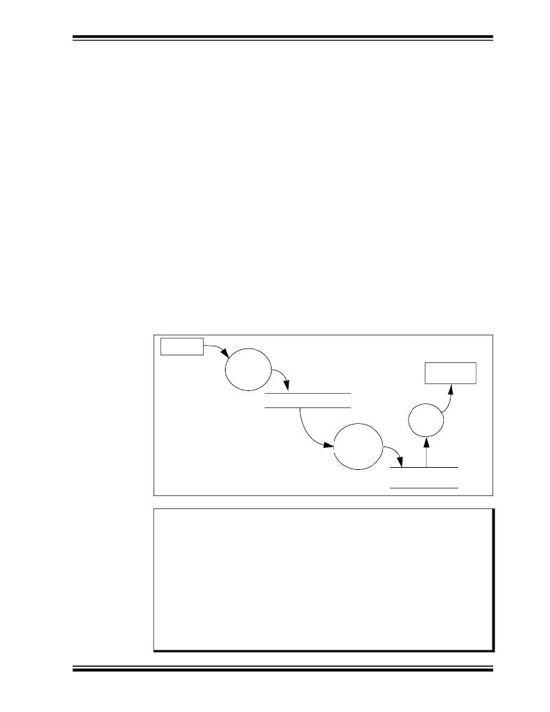
�The� acquisition� process� is� controlled� by� Timer0.� The� configuration� command� looks� up�
�precalculated� Timer0� prescaler� and� Timer0� values.� This� ensures� Timer0� will� generate�
�an� interrupt� on� time� as� specified� by� the� speed� configuration� parameter.� When� Timer0�
�overflows,� the� interrupt� is� triggered� and� initiates� an� analog-to-digital� conversion� and�
�restarts� Timer0.�
�Writing� to� a� serial� EEPROM� consists� of� writing� to� a� page� of� memory� (32� bytes� for� the�
�25LC640)� and� initiating� a� Write� cycle.� A� write� cycle� can� take� a� maximum� of� 5� ms� (3� ms�
�typical)� to� complete.� Thus,� in� order� to� store� A/D� conversions� at� high� speeds,� two� serial�
�EEPROMs� are� used.� The� data� conversions� are� stored� in� the� two� serial� EEPROMS� by�
�alternating� (interleaving)� between� the� two� devices.�
��FIGURE� 1-4:�
�PICA2DLAB� ACQUISITION� MODE� DATA� FLOW� DIAGRAM�
�ADC�
�Queuing�
�Function�
�(ISR)�
�Circular� Queue�
�Dequeuing�
�Function�
�(Acquisition)�
�Synchronous�
�Serial�
�EERead�
�EEPROM�
�(2x25LC640)�
�Note:�
�?� 2004� Microchip� Technology� Inc.�
�The� Signal� Analysis� PICtail� Daughter� Board� is� designed� as� a� development�
�tool� rather� than� laboratory� quality� equipment.� To� reduce� product� costs,� a�
�number� of� design� choices� have� been� made� in� favor� of� lower� cost� over�
�increased� accuracy.� These� choices� may� affect� the� accuracy� and�
�repeatability� of� measurements.� These� potential� sources� of� error� include:�
�?The� Analog-to-Digital� Converter� is� referenced� to� V� DD� ,� which� is� supplied�
�by� the� USB� cable.� The� PICkit� 1� Signal� Analysis� PC� Application�
�assumes� its� 5.00V,� however,� the� USB� specifies� only� 4.75-5.25V.�
�?Timing� of� the� samples� (in� Acquisition� mode)� is� controlled� by� Timer0� and�
�the� internal� oscillator� on� the� PICmicro� device.� Check� the�
�PIC16C745/765� 8-Bit� CMOS� Microcontroller� with� the� USB� data� sheet�
�(DS41124),� for� actual� specifications� on� oscillator� tolerances.�
�DS51476A-page� 11�
�发布紧急采购,3分钟左右您将得到回复。
相关PDF资料
AC164121
BOARD DAUGHTER PICTAIL ETHERNET
AC164122
BOARD DAUGHT PICTAIL SD/MMC CARD
AC164123
BOARD DAUGHTER ETH PICTAIL PLUS
AC164124
BOARD DAUGHTER IRDA PICTAIL PLUS
AC164125
BOARD DAUGHTER PICTAIL SPEECH
AC164127-3
BOARD DAUGHTER GRAPHIC PICTAIL
AC164127-5
BOARD GRAPH LCD CNTLR PICTAIL
AC164127-8
BOARD GRAPH DISPLAY 5.7 640X480
相关代理商/技术参数
AC164121
功能描述:以太网开发工具 Ethernet PICtail Dghtr Brd
RoHS:否 制造商:Micrel 产品:Evaluation Boards 类型:Ethernet Transceivers 工具用于评估:KSZ8873RLL 接口类型:RMII 工作电源电压:
AC164121
制造商:Microchip Technology Inc 功能描述:IC ((NW))
AC164122
功能描述:子卡和OEM板 PICtail Daughter Brd SD/MMC cards RoHS:否 制造商:BeagleBoard by CircuitCo 产品:BeagleBone LCD4 Boards 用于:BeagleBone - BB-Bone - Open Source Development Kit
AC164122
制造商:Microchip Technology Inc 功能描述:SEMICONDUCTOR ((NW))
AC164123
功能描述:以太网开发工具 PICtail Daughter Brd Ethernet Plus
RoHS:否 制造商:Micrel 产品:Evaluation Boards 类型:Ethernet Transceivers 工具用于评估:KSZ8873RLL 接口类型:RMII 工作电源电压:
AC164124
功能描述:子卡和OEM板 IrDA PICtail Plus Daughter Board RoHS:否 制造商:BeagleBoard by CircuitCo 产品:BeagleBone LCD4 Boards 用于:BeagleBone - BB-Bone - Open Source Development Kit
AC164125
功能描述:子卡和OEM板 PICtail Speech Playback RoHS:否 制造商:BeagleBoard by CircuitCo 产品:BeagleBone LCD4 Boards 用于:BeagleBone - BB-Bone - Open Source Development Kit
AC164126
功能描述:子卡和OEM板 PICtail Plus Proto Adapter Kit RoHS:否 制造商:BeagleBoard by CircuitCo 产品:BeagleBone LCD4 Boards 用于:BeagleBone - BB-Bone - Open Source Development Kit